


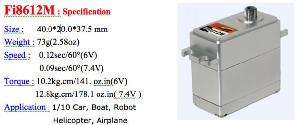
Standard HV programmable servo
Features
-Standard digital metal gears servo、2BB
-Coreless motor
-Waterproof
-Operating Voltage : 6~7.4Volts
-Interface: (like JR)
-Wire length: 30cm
Servo programmable function
1. FAIL SAFE, On or Off
2. Direction of Rotation
3. Travel Speed
4. Servo Max Torque limit, and Punch
5. Center, End, and FAIL SAFE Point
6. Signal Pulse Set-Up
7. Stretch (Holding Power, Running Power, Acceleration and Deceleration)
8. Dead Band Width
9. Resolution Setup
10.“Save and Open” File Options
11. Reset Factory Default Data
12.Read and Write Servo Data
Full Packaged
-Servo × 1PCS
-Servo arm × 1 bag
-Weight : 61g
Introduction
Thank you for using this USB interface to program FT digital servo and to test “all brand”servo. Please read this manual before useing the software and your new SCPC-1.
This SCPC-1 will allow you to easily check any servo brand’s servo performance by using servo test functions and set most of the programmable parameters of all FT digital servo types as noted in the following statement;
This SCPC-1 will program the following features of these FT digital servos:
Package Contents
Contents
- - One SCPC-1 USB interface device
- - One User’s Manual
- Required Optional Parts (Sold Separately)
- “Y” cable or USB extension cable
- One 4.8V or 6V “receiver” battery*.
*The SCPC-1 requires an external power source in order to test/program a servo.
WARNING: Be sure to use a fully-charged battery to prevent any data loss or damage during the programming process
Basic Set–Up Instructions
1. Download the SCPC-1 program software(ServoPC) from www.fitecrc.com. The SCPC-1 software is compatible with Windows XP and VISTA.
2. Plug the SCPC-1’s USB interface into your PC.
3. Start the ServoPC software from your PC.
4. Plug an external power source pack (4.8V or 6V battery) into the SCPC-1 ‘-+-’ slot.
5. A servo must be plugged into slot “S” in order to program or to test. The SCPC-1 supports only program one servo at a time.
Precautions and Warnings
1. Restart the PC if you can’t disconnect servo after start the ServoPC software.
2. DO NOT disconnect the SCPC-1 until programming is completed.
3. Disconnect the SCPC-1 interface if an error occurs during the programming process. 4. Use only a recommended power supply (4.8V, or 6V battery pack).
5. Restart the program if a servo reacts unstable during testing or programming.
6. Only one FT digital servo can be programmed at a time with the SCPC-1.
TEST MODE
Testing a servo’s function can be critical to completing a successful project. Use these tests to
“burn-in” new servos or to check for broken gears and other issues. The following Servo Travel tests can be performed on any brand of analog or digital servo on the market.
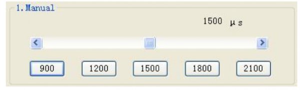
1. Servo Travel,
A. Manual Position
B. Automatic Sweep Position C. Step Positioning
2. FT Digital Servo FAIL SAFE programming position. This test is limited to FT Digital Servos only

- From the program’s home page, click “TEST” to select the servo test function options.
Note – Most modern servos use a signal from 900μs (at one end point) to 2100μs (the other end point) for their travel signal, with 1500μs being the default center point. This will be the standard for a servos movement range with the transmitters EPA settings at their maximum points.
Manual Position Test
- Use the pre-set buttons or click on the slide bar with your mouse to set a servo’s left and right travel endpoint.
- You are now ready to select which test to perform as per the following directions.
Automatic Sweep Position Test
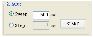
The “Auto-Sweep” function will cycle a servo over and over from end point to end point. Adjust the cycle value can to change servo Auto-Sweep speed.
- Select Sweep on the menu and click the START button. The servo will then move from end point to end point within its travel limits.
Automatic Step Position Test
A servo will automatically travel from end point to end point using a slow step movement using this function.
Automatic Step Position Test
A servo will automatically travel from end point to end point using a slow step movement using this function.
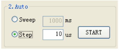
- Select Step and click the START button. Your servo will start moving from end point to end point in a series of small “steps”.Change the step value to adjust the servo’s travel speed.
FT Digital Servo FAIL SAFE Position Test
This feature will only test the user programmed FAIL SAFE point of FT digital servos. The FAIL SAFE point must be set by the user in the program section that Fail Safe is ON.
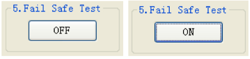
- By clicking the ‘OFF’ button and display “ON” button, the servo will travel to the preset FAIL SAFE position.
FT DIGITAL SERVO PROGRAM MODE

The following functions can be programmed into FT programable digital servos using the SCPC-1 Programmer;
1. FAIL SAFE, On or Off
2. Direction of Rotation
3. Travel Speed
4. Servo Max Torque limit, and Punch
5. Center, End, and FAIL SAFE Point
6. Signal Pulse Set-Up
7. Stretch (Holding Power, Runing Power, Acceleration and Deceleration)
8. Dead Band Width
9. Resolution Setup
10.“Save and Open” File Options
11. Reset Factory Default Data
12.Read and Write Servo Data
NOTE - To program a servo, be sure the SCPC-1 is interfaced with your PC, the red light is on,
a battery is plugged into the “-+-” slot and a FT Digital Servo is plugged into the S slot.
1. FAIL-SAFE On or Off
In selecting FAIL SAFE “ON”, you have chosen to set a user programmed FAIL SAFE travel point should the servo lose the receivers signal during normal operation.
- Turn the “FAIL-SAFE MODE” ON or OFF by clicking this button

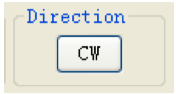
2. Direction of Rotation
- Switch your servo’s direction of rotation by clicking on the CW (clockwise) or CCW (counter clockwise) button.
3. Travel Speed
This feature is useful for users who do not have servo speed control functions on their transmitter. Servo speed control is a nice feature to slow down aircraft landing gear retract functions. The servo speed function will only slow a servo down. You cannot make a servo travel faster than its rated speed.
- Use this function must select “Enable” at first. And click on the slide bar with your mouse to ajust servo’s speed (0%) up to its maximum speed (100%). Please click the “SET” button after confirm speed value.
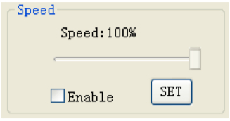
NOTE – Don’t set the speed lower than 15% ,if not will influence servo torque.
4. Servo Max Torque limit, and Punch
This feature is useful for users who want to protect servo when work on overload. Servo torque function will only limit the servo max power(current).You cann’t make the servo stronger than its rated torque. Punch is set the motor min power
-Click on the slide bar with your mouse to ajust servo’s torque (0%) up to its maximum torque
(100%). Please click the “SET” button after confirm torque value.
-When set the punch, if set too much force, it is possible to make the motor unstable.
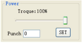
NOTE – Don’t set the torque lower than 15% ,if not will influence servo function.
5. End Point, Center Point and FAIL-SAFE Position Set-up and Reset
With the EPA setup, users can customize the center point and left/right servo travel end points.
If you choose “FAIL SAFE POSITION ON” in part 1 of the programming mode section, the FAIL SAFE position is selected at the Fail-Safe bar.
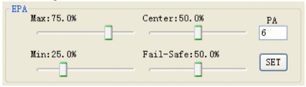
NOTE -Click “RESET” button for factory default EPA setting.
- Click on the slide bar with your mouse to ajust servo’s the center point and left/right servo travel end points.
- Move the slide bar to the desired FAIL SAFE position that you wish the servo to move too should it ever loose contact from the receiver during operation..
- After the EPA and FAIL-SAFE POSITION set-up are completed, Please click the “SET” button.
6. Signal Pulse Set-Up
This feature is useful for ROBOT FANS who want to Change servo contral pulse. The Min/Max slide bar is only limit the servo contral signal min/max pulse. The Center slide bar is setup servo center position’s contral signal.
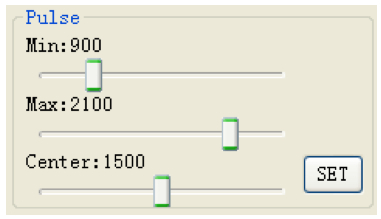
NOTE- Please don’t to change this setup if you don’t know your RC contral signal. If not, this setup will change servo EPA value and will harm servo.
- - Click on the slide bar with your mouse to ajust servo’s contral signal limit.
- - After setup are completed, Please click the “SET” button.
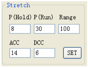
7. Stretch(Holding Power, Runing Power, Acceleration and Deceleration)
This function is a options design for advanced users.
This function is a options design for advanced users.
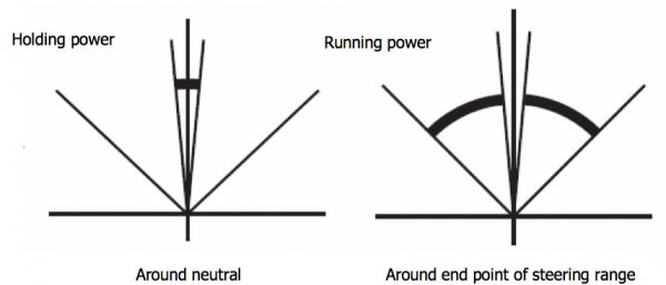
Holding power
Running power
Around neutral Around end point of steering range
Acceleration is a speed value that changed to start from stop.
Deceleration is a power value that let motor to stop from running.
These value need test yourself to confirm whether it is suitable for your use. -P(Hold) and ACC can be adjust the value from 1 to 50.
-P(Run) and DCC can be adjust the value from 1 to 255.
Deceleration is a power value that let motor to stop from running.
These value need test yourself to confirm whether it is suitable for your use. -P(Hold) and ACC can be adjust the value from 1 to 50.
-P(Run) and DCC can be adjust the value from 1 to 255.
8. Dead Band Width Setting
This function will allow users to set the center point “Dead Band Width” to one of five choices. Use this feature to adjust the sensitivity of a servo at the neutral position with the value of 1 being the most sensitive and 5 the least sensitive.
- Select the Dead Band Width value you wish to use. The value of “1” is the tightest and “5” the loosest.

9. Resolution Setup
This function will allow users to set servo travel angle “Resolution” to one of five choices. Use this feature to adjust the sensitivity of a servo at the moving with the value of 1 being the most sensitive and 5 the least sensitive.
- Select the Resolution value you wish to use. The value of “1” is the fastest and “5” the slowest.

10.“Save and Open” File Options
After programming your servo, you can choose to save the program to a file for future use.
The saved file can be copied to another servo or re-loaded into the same servo at a later date. Saving a File
After programming your servo, you can choose to save the program to a file for future use.
The saved file can be copied to another servo or re-loaded into the same servo at a later date. Saving a File
- When the servo setup is completed, click the “Save” button to store the data on PC. You will be prompted to name the file for future identification and to select a folder for the newly created .dat file.

Opening and using a Data file This function is used to copy a saved program into another servo of the same model number.
- Click the “Open” button and select the file you wish to use from previously saved .dat. Data files.

- Click the “Write ” button to save the data into servo.

11. Reset Factory Default Data
If you find an error in your servos program, or “to start all over”, you always have the choice to reset your servo to the factory default options.

If you find an error in your servos program, or “to start all over”, you always have the choice to reset your servo to the factory default options.
12.Read and Write Servo Data
If you want to knowe your servos all data, please cliek the READ button. Y
- Click the “Write ” button to save the data into servo.
11. Reset Factory Default Data
If you find an error in your servos program, or “to start all over”, you always have the choice to reset your servo to the factory default options.
If you find an error in your servos program, or “to start all over”, you always have the choice to reset your servo to the factory default options.
12.Read and Write Servo Data
If you want to knowe your servos all data, please cliek the READ button. Y

Click the “Write ” button to save the data into a different servo.

Upgrading Firmware